Do you know how significantly the pickup nozzle affects the accuracy of a pick-and-place machine?
Published Time:
2026-09-18
Mount surface technology (SMT) equipment centers around the placement machine, where precision directly dictates production yield and product reliability. As components shrink to 0201, 01005, and microscopic active chips, placement tolerances are routinely measured in single-digit microns. When offset errors, component dropping, or tombstoning occur, engineering teams often inspect vision systems, linear encoders, or servo motors first. However, the root cause frequently traces back to the smallest consumable in the machine: the suction nozzle. As the only physical interface between the machine head and the component, any geometric imperfection, material wear, or pneumatic instability in the nozzle amplifies into significant placement deviation. Physical Mechanisms: How Nozzles Affect AccuracyDuring the milliseconds between pick-and-place, the suction nozzle impacts precision across three primary physics vectors: Pick Orientation & Z-Axis Tilt: If the nozzle tip exhibits uneven wear, chipping, or solder flux contamination, the component will tilt or shift off-center during picking. While 2D vision cameras correct planar errors, they cannot fully compensate for spatial Z-axis tilt. During placement, a tilted component contacts the solder paste asymmetrically, creating micro-fluidic displacement that pushes the component off-target. Optical Vision Interference: Placement machines use upward-looking optical recognition to compute offsets. Scratched anti-reflective coatings, oily reflective plates, or degraded black-oxide surfaces generate edge artifacts or change contrast ratios, leading the vision algorithm to miscalculate the component's true center. Pneumatic Instability & "Secondary Blow-Off Shift": Vacuum holds the component against acceleration forces reaching up to 5G. Partial nozzle blockages or poor tip seals cause pressure fluctuations, allowing inertial displacement during high-speed travel. Furthermore, during the positive-pressure release phase (blow-off), uneven air blasts can physically displace the component off the solder pad. 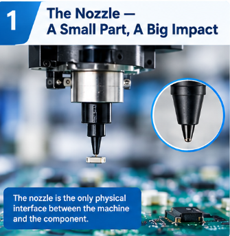 Primary Causes of Nozzle-Induced Errors
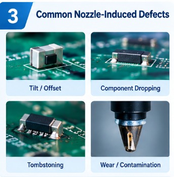 Material Selection & Precision CharacteristicsSelecting the right tip material serves as the first line of defense against long-term placement drift: Tungsten Steel (Carbide): Highly durable with exceptional machining tolerances. Excellent for micro-apertures, though heavier mass can introduce slight momentum at ultra-high speeds. Requires anti-static coatings to prevent ESD-induced misalignment. Ceramic: Extremely lightweight, non-magnetic, and inherently anti-static with zero thermal expansion under high-frequency operation. Ideal for 0201/01005 components and dense BGA placement. Polymer / Diamond-Coated / Rubber: Rubber tips provide superior vacuum seals for irregular or delicate packages (like glass-passivated dies), but degrade quickly. Aged rubber tips cause significant Z-height deviations over time. Best Practices for Nozzle Management Maintaining sub-micron precision requires an active maintenance framework: Automated Preventive Maintenance (PM): Implement automated ultrasonic cleaning cycles to strip internal flux build-up. Utilize dedicated nozzle inspection systems to evaluate tip flatness, concentricity, and optical surface integrity. In-Line Auto-Calibration: Leverage Auto Nozzle Changers (ANC) and station cameras to run automated center-offset and height calibrations between production batches. Lifecycle Tracking: Enforce strict aperture-to-package matching criteria (EIA standards). Track total pick counts in the MES database, retiring nozzles once they hit vendor life-cycle thresholds (typically 500,000 to 800,000 actuations). In modern SMT manufacturing, precision lives at the tip of the nozzle. Controlling air dynamics, material wear, and surface geometry at the contact point remains one of the most cost-effective ways to optimize placement yield and reduce rework. |


No. 739, Zhou Shi Road, Hezhou Community, Hangcheng Street, Baoan District, Shenzhen



Copyright © 2025 Shenzhen ETON Automation Equipment Co., Ltd. ALL Rights Reserve.